CM-Cabinets Library User Guide
In This Topic
    Edge Pulls in DoorMaster LT
    In This Topic

    Edge Pulls are the routing along (and into) the edge of a door or drawer front that acts as a 'handle' to open it. 

    There are a variety styles (for example 'J Pulls' or 'C Pulls') and can be placed on any edge (or multiple edges) of a door/drawer front.  They may or may not extend the full length of the edge.  


    Edge Pulls in DoorMaster LT

    Currently the following DoorMaster LT doors include the ability to add Edge Pulls:

    For doors with the ability to add Edge Pulls there are a number of default/saved settings that can be adjusted via catalog, drawing and/or cabinet property pages.

    If you purchase a licence to enable Machining,  you will still need to setup the tooling and strategies in EzyNest to machine this profile.

     Drawing Properties for Edge Pulls

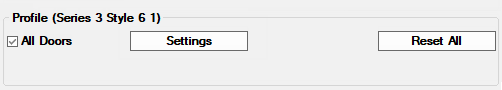
    Profiles can be selected and viewed/edited on the DoorMaster LTProfile Doors page of the Catalog/Drawing Properties.

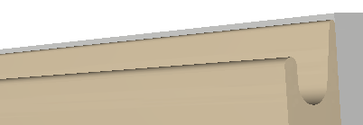
    Simply select the Series, Style and Version from the drop lists, in this case the Series 3 Style 6 as shown.

    Ensure the Profile is On and if you want to use Machining then the purchase of the applicable licence is required.

    Click to Expand

    Click to Expand

    Click on the image to open the selected Profile's Properties which allows you to view, change and save new settings.

    • The chosen door's settings include an Edge Pull category with six (6) associated pages.
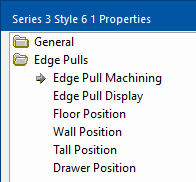
     

    Edge Pull Machining

    The Edge Pulls > Edge Pull Machining page provides the options to input the required Pull Machining Settings.

    When machined on a flatbed router where the parts are nested together, doors/fronts with Edge Pulls are spaced apart to allow for the tooling along the edge. This is because the Edge pull profiling tools are often quite wide and require a pocket for entry/exit as they cannot be plunged.

    To avoid damaging the machine and board it is important that these settings are correct (along with the tool strategies in the nesting/machining software used - see Nesting and Machining Notes below).
    Edge Pull Machining  -  Click to view Page Options

    Edge Pull Machining  -  Click to view Page Options

    Explanation of Options

    Options

    Explanation

    Clearance The gap between the Edge Pull tool and the side of pocket (to ensure there is a sufficient margin when the Edge Pull tool is plunged into the pocketed area).
    Edge Overlay The distance the centre of the Edge pull tool pushes into the side of the door.
    Pocket Overlay The distance the pocket overlaps the edge of the door.
    Pocket Depth The depth of the pocket.
    Pocket Layer The dxf layer name for the pocketing tool path.
    Pocket Tool Radius The radius of the pocketing tool.
    Profile Depth The depth the Edge Pull tool is plunged to (this is usually the same or very slightly less than the pocket depth).
    Profile Layer The dxf layer name for the Edge Pull toolpath.
    Profile Tool Radius The radius of the Edge Pull tool.
    • The size of the pocket is determined by the Edge pull tool radius and clearance. 
    • The exported machining also includes an additional spacing dxf layer to ensure other parts are not nested where the Edge Pull tool will route.
    • See Nesting and Machining Notes below for further machining information.


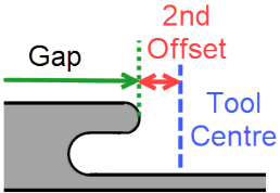
    Length of Edge Profile Tooling

    The toolpath for the Edge pull profile is calculated so that the specified gaps, set on the Edge Pulls > Cabinet Positions page, are measure to the edge of the physical door front accounting for the shape of the tool as shown below. This means the calculation uses the Second Offset found on the Edge Pull Display page.

    If the gap is set to be zero however (so that the Edge profile runs the entire side of the door), then the 2nd Offset is ignored and the tool runs an extra 1mm beyond the edge of the door.

    Pocket Size

    The pocket size is calculated using the width of the profile tool and the clearance.  However, if the Pocket tool is larger than the profile tool plus the clearance on both sides, then the Pocket Tool's width is used instead.


    Edge Pull Display

    The Edge Pulls > Edge Pull Display page allows the look of the 3D can be adjusted using these settings. 

    The actual Edge Pull tool settings also have an influence.
    Edge Pulls > Edge Pull Display  -  Click to Expand

    Edge Pulls > Edge Pull Display  -  Click to Expand

    The 3D will adjust to a best fit using these setting, but will try and not corrupt if the settings are out of a usable range. For example, if the defined 3D shape is wider than the thickness of the material.

    Do not go back and adjust the Edge pull tool depth, radius or overlay just to get the 3D looking good as this will affect the actual machining!


    Position - Floor, Wall, Tall, Drawer

    The Edge Pulls > Cabinet Position pages options control the positioning and side of the Edge Pull on the different doors types and drawer fronts.

    The Edge Pulls can be enabled on the different edges of the door with the measurements defining any gap each side of the Edge Pull profiling.

    The available positioning properties are similar between the different types, although the Tall doors and Drawer fronts vary slightly.
    Edge Pulls > Floor Position Page  -  Click to Expand

    Edge Pulls > Floor Position Page  -  Click to Expand

    There are drawbacks in specifying default settings for Edge Pull side and its gaps for all doors of a certain type:-

    • The hinged side may vary from door to door.
    • The dimensions of each door may vary.

    The following settings compensate for this.


    Smart Enables

    The Smart Enables specify the settings to be used on the natural Handle Side of the door (i.e. the opposite side to the hinge).

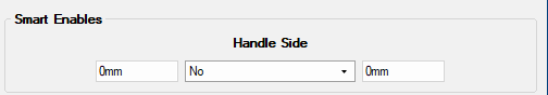
    The gap measurements here are taken as if being viewed from the centre of the door outwards towards the profiled edge.

    For example, if the handle side was on the Left of the door then the Smart Enable gap to the right of the Yes/No will be towards the top of the door and the one on the left would be used on the bottom (and visa versa if handle was on the Right side of the door).

    Also note that:-

    • Smart enabled profiles will be in addition to any others specified.
    • Smart Enables are not available on Drawer fronts - see Extras for Tall and Drawer


    Centre and Use Length

    Setting the Centre and Use Length option to Yes will ignore any gaps specified to each side of the Edge Pull profile. 

    The Edge Pull will be centred along the side of the door and be of the length specified (leaving even gaps to each side).

    Edge Pulls  Position  -  Click to Expand

    Edge Pulls  Position  -  Click to Expand


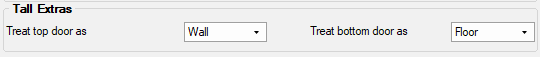
    Extras - Tall and Drawer

    Extras are only available for Tall doors and Drawer Fronts.

    Tall Doors

    For doors in Tall cabinets it may be that the Edge Pulls are placed along the 'Handle Side', but when there is a pair of doors (one above the other) the Edge Pull position may need to be different.  For example, an upper door may need the Edge Pull along its bottom side and the lower along its top.

    The Extras allow these doors to be treated as if they were of a different type.

    Drawer Fronts

    Similarly with Drawers Fronts, the top and bottom drawer fronts on a set of drawers may need to be treated differently from the ones in-between.


     Cabinet Settings

    The Edge Pull positioning settings can be adjusted per cabinet, area of cabinet or individual door using the Settings button on the Materials > Doors page (or Materials > Drawer Fronts page).

    Located on Materials > Doors page or Drawer Fronts page

    Located on Materials > Doors page or Drawer Fronts page


    Override Drawing Properties

    To override the current drawing default settings click on the Override Settings button.

    You will be asked 'Are you sure you want to override?' to confirm that you wish to continue.
    Edge Pulls > Door Positions page has an Override Settings button

    Edge Pulls > Door Positions page has an Override Settings button


    Clicking on the Override button allows you to adjust the positioning options for the chosen door/s.

    Note that the 'Override' button is replaced with a Reset button which can be used to remove the local setting and revert back to the defaults.

    Edge Pulls > Door Positions page is made available to enable adjustments  -  Click to Expand

    Edge Pulls > Door Positions page is made available to enable adjustments  -  Click to Expand


    Drawer cabinets  have a Select Position Individually for Each Drawer checkbox to allow the presence of the edge pulls on each side of each drawer front. Otherwise the same settings are used for each.

    Edge Pulls > Edge Pull Positions for Drawer Cabinets

    Edge Pulls > Edge Pull Positions for Drawer Cabinets


    Extra Notes

    Using Edge Pulls

    You need to take into consideration the following points:-

    1. Be aware that the presence of an Edge Pull does not automatically turn off any Handles and their associated machining.

    2. Drawerbanks (a bank of drawers cut as one door) DO NOT support Edge Pull machining or 3D representation.

    3. Do check the desired Edge Pull positioning on cabinets as not all circumstances can be automated, for example:-
      • On a Tall Cabinet with a pair of doors (one above the other), it may be desirable to have the Edge Pull on the bottom of the upper door and the top of the lower. But, if the lower door is quite high it may need to be on its side and therefore the cabinet may need to be locally adjusted.

      • Universal Cell doors cannot be adjusted individually.


    Nesting and Machining

    The following must be taken into consideration when Nesting and Machining:-

    1. Edge Pull tools are often quite wide and require a pocket for entry/exit as they cannot be plunged.
    2. The size of the plunging pocket used by DoorMaster LT is determined by the Edge Pull tool Radius and Clearance
    3. The Pocket toolpath defines the outside of the pocket.
    4. The Edge Pull toolpath defines the path of the centre of the tool (i.e. it is an 'on-line' or 'engrave' path).
    5. To avoid damaging the machine, tool and/or board it is important that the tool strategies are correctly configured.
      • Ensure the Edge Pull tool properties are correctly defined in DoorMaster LT.
      • Ensure the depth of the plunge Pocket is sufficient for the Edge Pull tool to be plunged into.
      • Ensure any Entry or Exit strategies used in your nesting/machining software (e.g. EnyNest, EnRoute etc) for the Edge Pull does not take the tool outside the pocket during these operations (e.g. a 90deg entry may land the tool on the board outside of the pocket).
      • Ensure that the feed and speed rates are appropriate.
    6. The exported machining includes an additional spacing dxf layer (using the CabMaster layers table 'SpaceMe' name) to ensure other parts are not nested where the Edge Pull tool will route. This is not to be machined, but should be included in the nest.